The Sketch Driven Pattern tool is an underused, but very useful tool. Typically, when we pattern items in SOLIDWORKS we tend to use linear or circular patterns, but what happens when we want to pattern an item where the spacing between instances is irregular or random? That’s where the Sketch driven pattern tool comes into its own.
Where is the Sketch Driven Pattern tool?
You’ll find the tool on the features toolbar on the drop-down menu of ‘Linear Pattern’ as per the below image:

How does the Sketch Driven Pattern tool work?
Create a sketch that contains sketch points. Next, select that sketch as the reference within the Sketch Driven Pattern tool (as well as the features you wish to pattern) – an instance of the features will be created wherever there is a sketch point within that sketch.
Let’s take a look at an example.
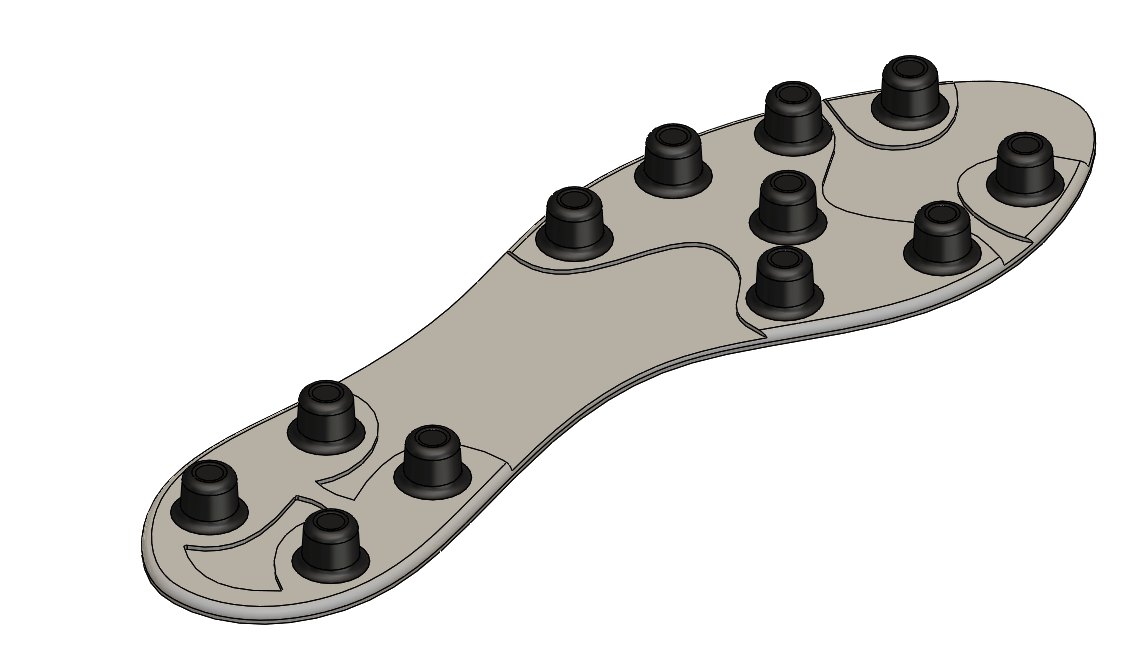
We’re looking to create the sole of the football boot as per the below image:
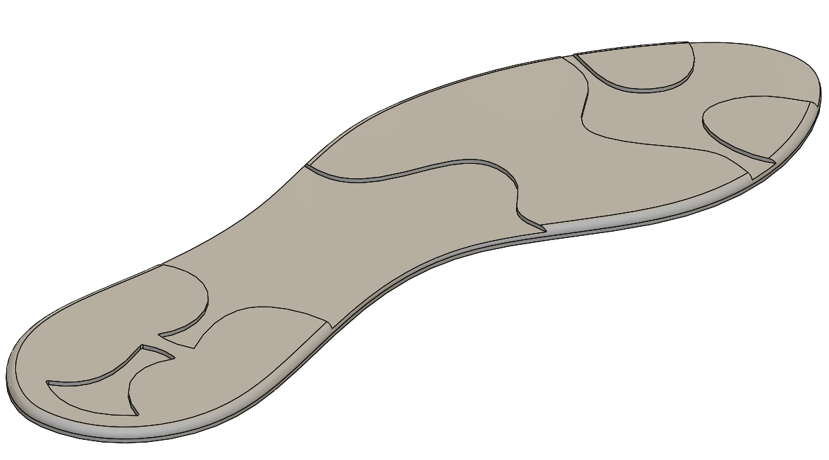
We’ve have started the model by creating the sole of a football boot:
We then create one of the studs…
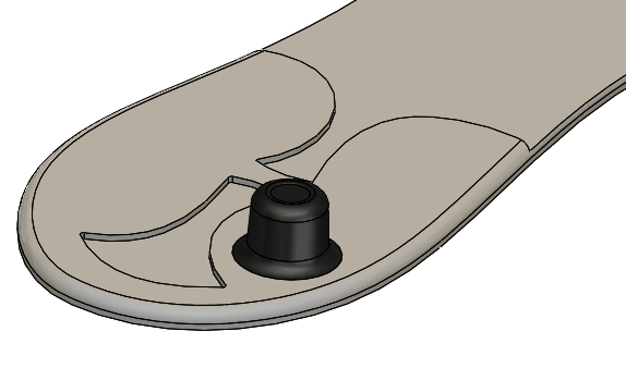
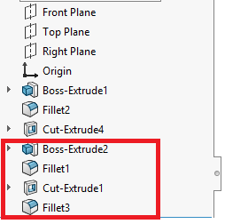
…which is made up of several features:
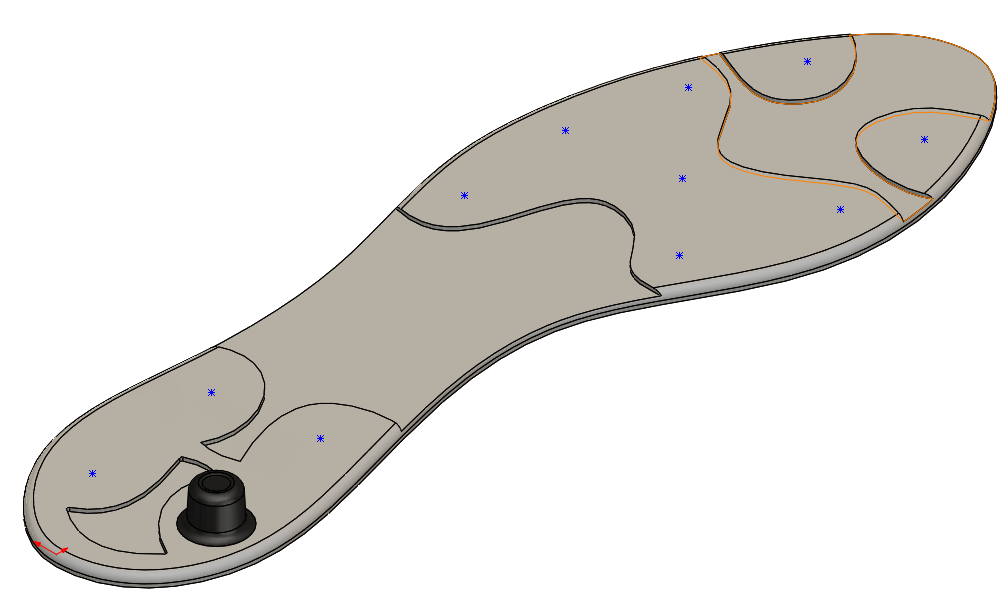
We then create a sketch on the top face and add several sketch points:
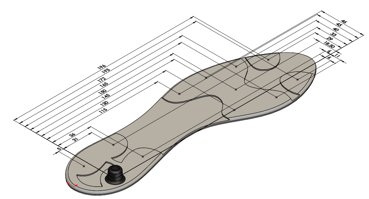
The sketch points in the above image are under-defined. To quickly fully define the points, simply use the fully define sketch tool found on the drop-down of ‘Display/Delete Relations’ on the sketch toolbar:

This will allow you to dimension your sketch points horizontally and vertically from a reference of your choosing at the click of a button:
Now exit the sketch and launch the Sketch Driven Pattern tool. This will ask you for the reference sketch (this will be the sketch containing the points) and the features you wish to pattern (these are the features that make up the stud):
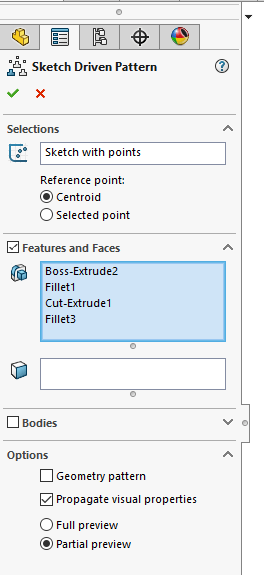
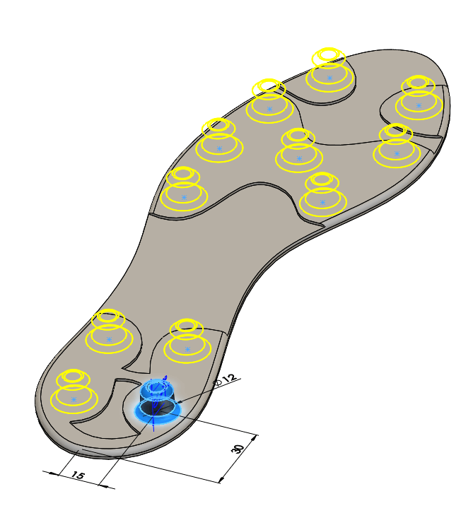
As you can see from the above preview, an instance of the stud is created wherever a point is placed within the sketch. All we need to do is ‘OK’ the feature to complete the model. If we decide we want to add or remove instances of the stud, simply edit the sketch (that contains the sketch points) and add or delete the points from the sketch.
Things to be aware of when using the Sketch Driven Pattern tool:
When using the Sketch Driven Pattern tool, you are given the option to choose a reference point to pattern about. This can be either the centroid or a selected point.
Let’s have a look at what this does.
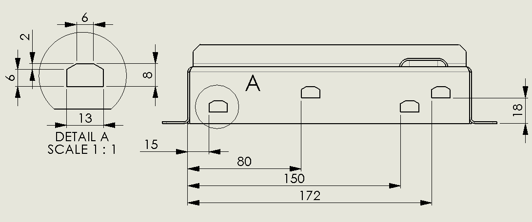
In the below example we have a sheet metal part with a cut out in the back (Detail A). The cut out needs to be patterned across the back face in 4 places. The dimensions given on the drawing for the location of the holes are to the bottom left hand corner as per the below image:
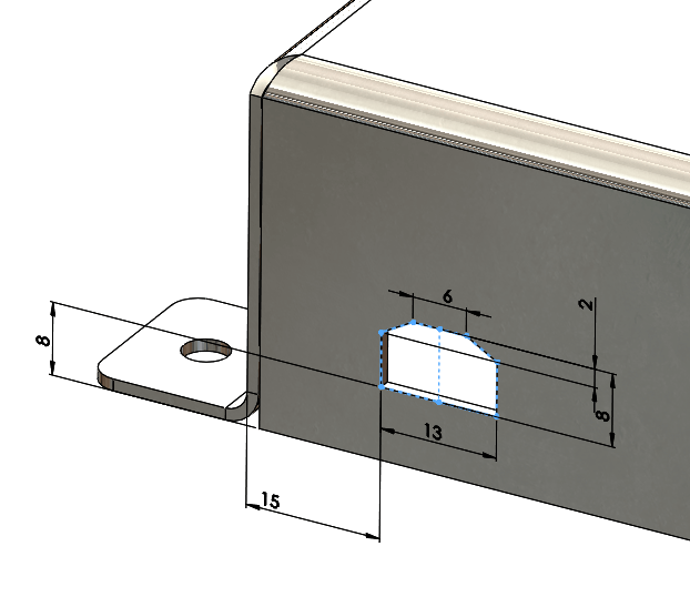
We generate our first cut out using the cut extrude tool using the same dimensions as per the drawing:
We then lay out our sketch for use with the sketch driven pattern, again matching the dimensions that are given on the drawing:
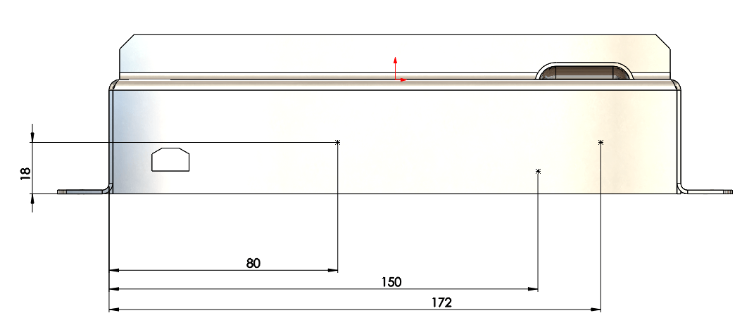
We then create our sketch driven pattern using the sketch and feature. As you can see from the below preview, the feature is patterning about its centroid which is not correct in this case:

Therefore, to get this to pattern as intended, I use the selected point option and choose the bottom left hand vertex of the cut out as our reference:

This then places all the patterned instances in the correct positions as per the drawing (with the left hand corner of the cut out attached to the sketch point).
Can I use Sketch Driven Pattern with a 3D sketch?
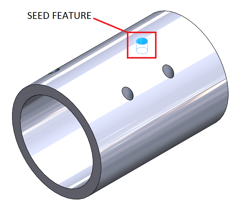
It is possible to pattern using a 3D sketch, but you must be aware the feature will pattern in the same orientation as the seed. For example, if I placed a hole in a shaft which cut normal to the surface, then placed a number of sketch points along the cylindrical face of the shaft in a 3D sketch and used those items as for a sketch driven pattern, the patterned holes solve in the same orientation as the seed feature (rather than normal to the face):
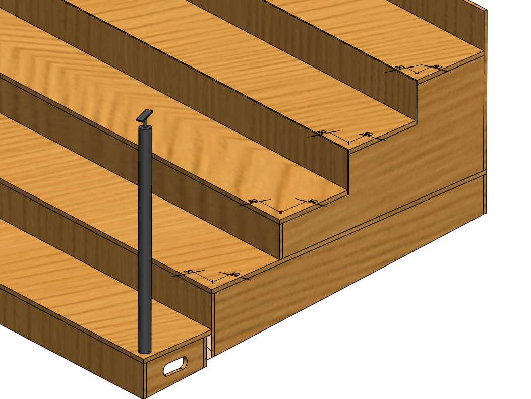
An example of where we could make use of a 3D sketch within the sketch driven pattern tool is where we are patterning handrail posts up a flight of steps.
If you look at the below image, you’ll see we’ve created our handrail and then generated a 3D sketch, where we’ve placed a series of sketch points 50mm from the front and side face of each tread:
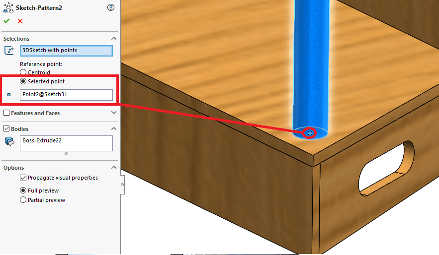
We are now ready to pattern the handrail post. When using the sketch driven pattern tool, we select bodies to pattern as this is a weldment part. We also need to define a reference point. This is the bottom centre of the handrail post.
As you can see from the following image, we get the desired effect:
The handrail posts are now complete!
Hopefully you can see that the sketch driven pattern tool can be extremely useful and can be used as an alternative to the more commonly used patterning tools in certain circumstances.
We hope you found that useful!
Have you seen our blog archive where we have posted plenty of helpful articles? We also have a fantastic video library filled with easy-to-follow videos on a number of topics inspired by other SOLIDWORKS users – take a look. Also, don’t forget to follow Innova Systems on twitter for daily bite size SOLIDWORKS tips, tricks and videos.


