In order to get the most realistic renders possible out of SOLIDWORKS Visualize, it’s sometimes the case that you will need to modify your SOLIDWORKS Model. For example, adding a natural/organic form to a design which may be too uniform. There are some easy tricks you can use here to modify the geometry to your liking, the best examples of which will be covered in this tutorial.
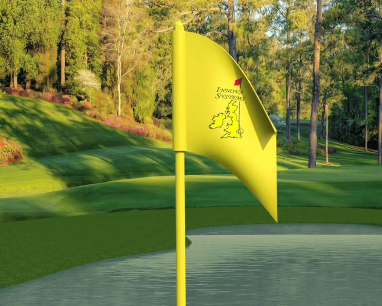
This flag is a good example of something that could do with some work in order to make it look more realistic and less uniform.
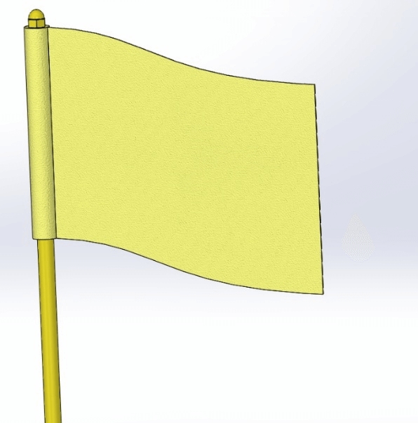
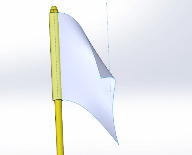
The Surfacing tools can be useful when modelling more organic shapes. In this example, two sketches have been drawn (shown in blue). These have been joined together with a surface loft. Found on the Surfaces toolbar > Surface Loft
All that needs to be done after this stage is to widen the profiles using the Thicken tool. Also found on the surfaces toolbar.
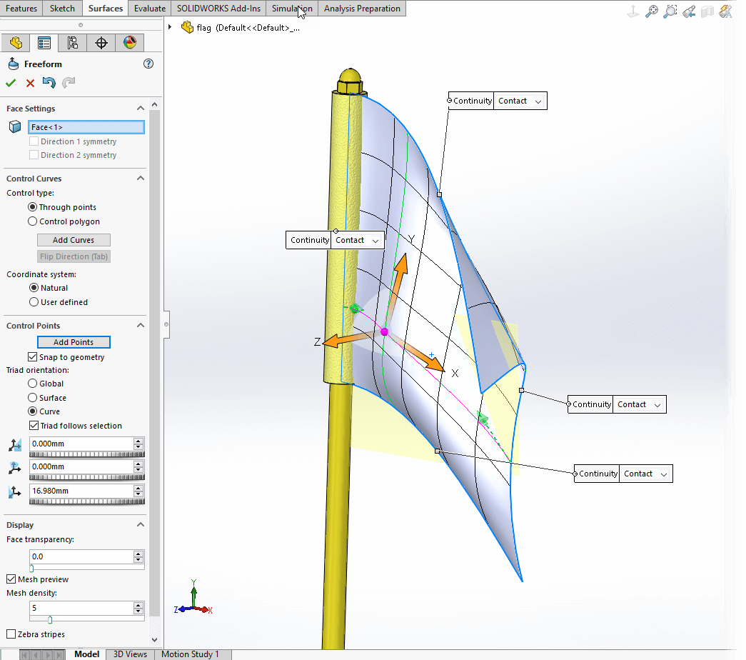
The Freeform tool can be useful when trying to modify existing geometry. When using this tool keep in mind:
- It works better if your design is made up from one large face. It won’t work if you have lots of smaller faces
- You will need to initially add curves, then add points to those curves (shown in the property manager)
- When you select a point after placement a triad will appear which will allow you to drag to change the location of a point
It’s usually not advisable to drag the point in line with the surface, movement should usually be roughly normal to the surface position.
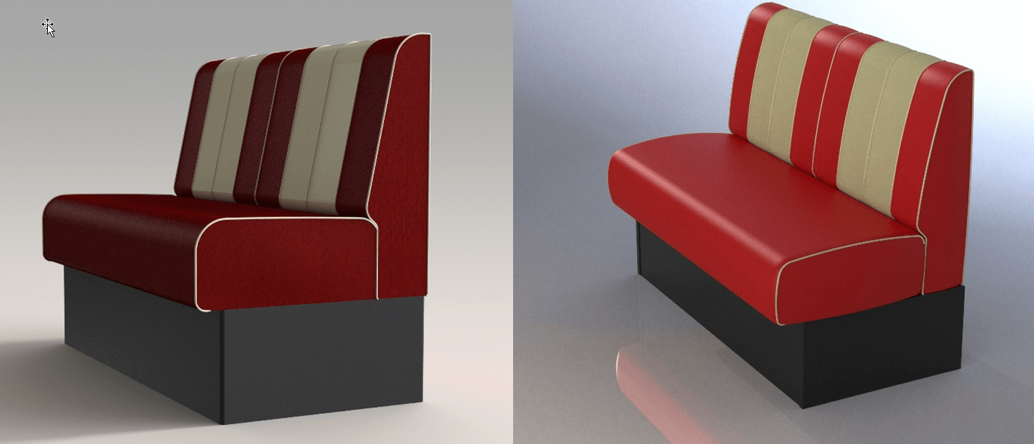
In this example in order to make this chair appear more realistic, a series of extrude and revolve cuts were used. We cut away areas of the model to create a design which looked more like it had cushions, rather than being made from a solid material.
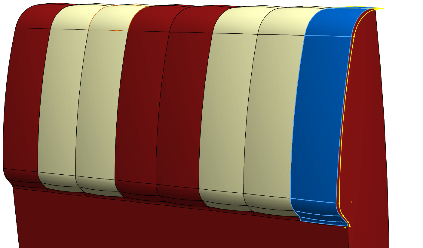
Another option is to add in additional geometry, for example, this sweep used in the top seat cushion. Here, this feature is patterned across the design.
Keep in mind that no design is manufactured with perfectly sharp edges, so adding in some fillets is a superb way to catch more highlights in a render. This is true of any model going to render, so it’s a process we will almost always do.
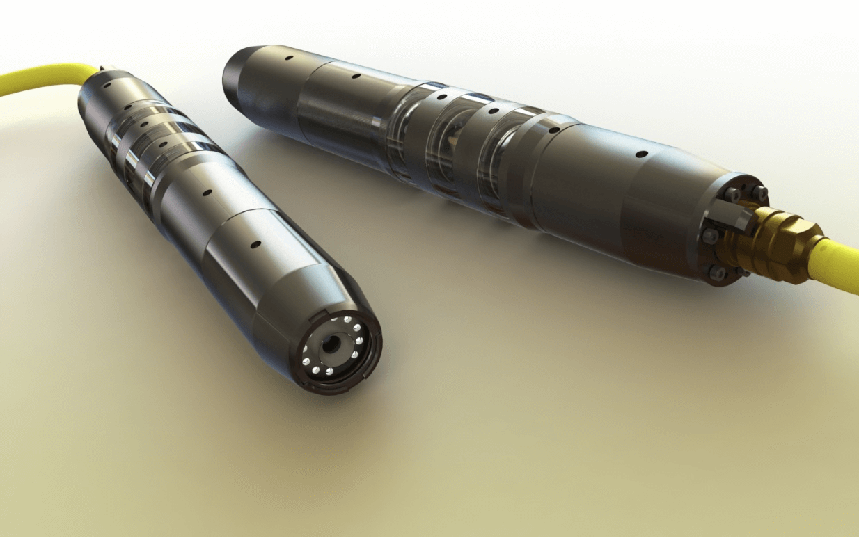
In this example sweeps can also be used to model in simple Cables/Wires. Modelling these going out of view suggests that the item might be connected to something.

Keep in mind that you don’t have to model everything in your designs. These servers look like they have been fully detailed. In fact, the servers in this rack are made up from simple designs that have had an image (decal) placed on the front face. The only geometric addition that was made was adding in small geometry for the LED lights.
Adding geometric detail and into your renders is a key step to get them looking as realistic as possible. In this tutorial we’ve covered some of the quick tricks you can use to quickly improve your renders. Hopefully it provides an insight into how we create some of our renders using SOLIDWORKS Visualize.
Before you go…
Check out these related posts:
- Using bump maps in appearances
- Using displacement maps in Visualize
- Texture Mapping & Scaling in SOLIDWORKS Visualize
- Using backplates when rendering in SOLIDWORKS Visualize
We hope you enjoyed learning about Modifying SOLIDWORKS models to add realism to renders.
Have you seen our blog archive where we have posted plenty of helpful tutorials and news articles? We also have a fantastic video library filled with easy-to-follow videos on a number of topics inspired by other SOLIDWORKS users – take a look. Also, don’t forget to follow Innova Systems on Twitter for daily bite size SOLIDWORKS tips, tricks and videos.


