When working in sheet metal, we need to be able take a folded sheet, flatten it, and have an accurate size flat pattern. In SOLIDWORKS this is achieved by selecting the relevant bend allowance options in the Sheet Metal tool. The three main options that you will select between are:
- KFactor
- Bend allowance
- Bend Deduction
KFactor
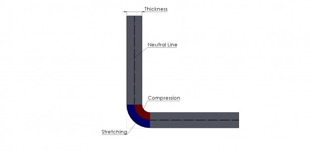
This method calculates the flat pattern based on the neutral line of the material. When we have a fold in a sheet metal part there is compression and stretching of the material. The neutral line lies between the transition of stretching and compressing of material as shown in the below image.

The location of the neutral line varies based on the material used.
When we define Kfactor as our bend allowance, we are telling SOLIDWORKS where that neutral line is. This is achieved by specifying a number between 0 and 1. The number is a ratio that relates to the thickness of the material (where 0 is inside of the material and 1 is the outside). Therefore if we specify a Kfactor of 0.5, the neutral line will be halfway through the thickness of the material.
The Flat pattern is then calculated based on the length of the neutral line. As shown in the below image.

Based on the above example the developed size of the sheet should be 203.5 (90+90+23.5).
Bend Allowance
Bend allowance allows the user to calculate the developed size of the sheet metal part based on a value which the user defines that represents the bend region. If we look at the example below, you will see that that we have 2 dimensions that go from the end of the sheet to the outside setback (start of the bend region on the outside of the sheet). If we were to define a bend allowance of 5mm, the developed size for the sheet would be 185 (90+90+5).


It is possible to add any value for the bend region, so it is possible to get very unrealistic results.
Bend Deduction
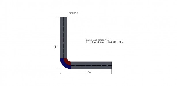
Bend deduction allows the user to calculate the size of the developed sheet by subtracting a value from the external dimensions of the sheet. In the below example we will specify a bend deduction of 5mm – so our developed sheet size would be 195 (100+100-5)

The maximum value the bend deduction can be is 2 x the outside setback.
Where can problems occur?
The most common issue we come across is where people use bend deduction, and do not adjust the bend deduction value for non 90 degree bends. This is especially true where we have acute angles. In the below example we have a 30 degree bend. The outer dimensions for this sheet are taken from the virtual sharp – which as you can see sit a fair distance away from the model and give us a large outside setback region. Therefore our developed sheet size is 269mm (137+137+5), which is actually much bigger than it should be.

To get a more accurate result, our bend deduction value should change (increase in the above example) based on the angle we are bending to. This is the reason bend tables are used. They allow us to define to automatically select bend deduction value based on the angle we are bending to and the thickness of the sheet. Kfactor & Bend allowance tables are also available.
Which Bend Allowance type should I use?
You should talk to the manufacturers of the part to see what bend allowance you should use. Some will be able to provide you with exact values or tables directly from their press break handbook. Some will tell you not to provide the flat pattern & that they will calculate either manually or by taking a copy of your model. If you are not sure what to use, I would suggest using kfactor at 0.5 because it will give you developed sheet sizes fairly close to what it should be, alternatively, as a general rule we would subtract 2 thicknesses of the sheet per 90°bend – Which is what I used when I was working in the industry.
We hope you enjoyed learning about Bend Allowance in SOLIDWORKS.
Have you seen our blog archive where we have posted plenty of helpful tutorials and news articles? We also have a fantastic video library filled with easy-to-follow videos on a number of topics inspired by other SOLIDWORKS users – take a look. Also, don’t forget to follow Innova Systems on Twitter for daily bite size SOLIDWORKS tips, tricks and videos.


